


How Angle Selection Affects Moldpartsfactory Inclined Ejector Slide in Ejector Injection Molding
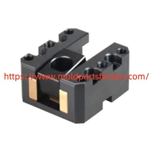
Inclined Ejector Slide supports clean release of parts that feature undercuts or angled surfaces inside intricate cavity layouts. The degree of tilt controls how far the unit travels sideways while the plate moves forward. Selecting an appropriate band keeps motion smooth and reduces stress on both the plastic part and the surrounding steel.
In practice the usable span sits between three and fifteen degrees. Many working tools stay inside three to eight degrees because this band balances lateral travel against mechanical load. A shallower setting needs longer plate movement to clear the same undercut depth. A steeper setting shortens the required stroke yet raises side force on the guiding surfaces. When the tilt exceeds twelve degrees designers often add a parallel support rod so the main body does not bend under repeated cycles.
Ejector Injection Molding benefits from careful matching of tilt to available plate travel. The basic relationship follows the tangent function: required side movement equals plate stroke multiplied by the tangent of the chosen degree. Adding a small safety margin of half a millimeter to one millimeter beyond the undercut depth prevents the part from catching during return. For a four millimeter undercut and a forty millimeter plate stroke the resulting tilt falls near six degrees, a value that remains well inside the preferred band.
Space constraints inside complex cavity layouts further influence the choice. When cooling channels inserts or other moving elements leave little room a modest tilt allows the unit to fit without interference. Harder steels or coatings on the sliding faces help manage friction at the higher end of the range. Soft materials or thin wall sections call for gentler tilts so the part does not distort under the applied force.
Material of the plastic itself also plays a part. Higher shrinkage resins may need a slightly larger clearance and therefore a small adjustment in tilt. Surface texture on the undercut wall can increase drag and push the designer toward the lower end of the range. In each case the goal remains the same: enough side travel to free the feature while the plate stroke stays within the limits of the mold base.
Wear patterns change with the selected degree. Steeper tilts concentrate load on the contact faces and can accelerate galling if lubrication or coating is inadequate. Shallower tilts spread the load yet demand greater overall height in the tool. Regular inspection of the guiding surfaces after initial runs confirms that the chosen setting performs as calculated.
Moldpartsfactory supplies ready to machine blocks and complete units that accept a range of tilts so toolmakers can adapt the component to each project. Custom machining of the working face to match the part contour is available when standard sizes do not fit.
Proper documentation of the final degree stroke and clearance values helps future maintenance teams. Recording the calculated side travel and the actual measured result after first shots creates a reference that shortens later adjustments. When multiple units operate in the same tool keeping their tilts consistent simplifies plate motion and reduces the chance of uneven force.
Engineers who need standard or custom units for detailed cavity work can review current options and request drawings at https://www.moldpartsfactory.com/

 English
 Arabic
 French
 Spanish
 Portuguese
 Deutsch
 Dutch
Dutch
 Italiano
 Russian
 Romaian
 Portuguese (Brazil)
 Greek
Greek