


RF Cable Assembly: How to Choose the Right Cable and Connector
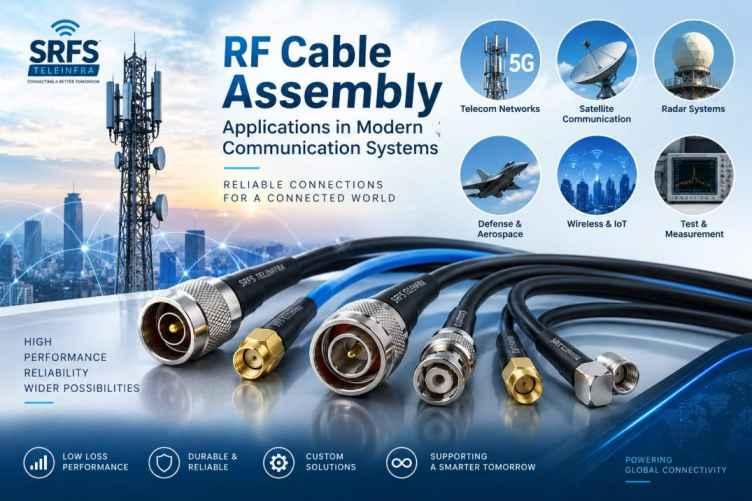
Choosing the right RF Cable Assembly is essential for maintaining reliable signal transmission, minimizing signal loss, and ensuring consistent performance in modern communication and electronic systems. RF cable assemblies combine a coaxial cable with suitable RF connectors to create a ready-to-install solution for transmitting radio-frequency signals.
From telecommunications and wireless networks to radar, satellite communication, test equipment, and industrial electronics, the performance of an RF Cable Assembly can directly affect the efficiency and reliability of an entire RF system. Selecting the correct cable, connector, length, and electrical specifications is therefore important for achieving optimal results.
What Is an RF Cable Assembly?
An RF Cable Assembly is a pre-terminated coaxial cable fitted with RF connectors at one or both ends. The assembly is designed to transfer high-frequency electrical signals between antennas, RF equipment, transmitters, receivers, filters, amplifiers, test instruments, and other components.
A typical RF cable assembly consists of:
-
Coaxial RF cable
-
Center conductor
-
Dielectric insulation
-
Conductive shield
-
Protective outer jacket
-
RF connectors
-
Connector termination
The cable and connectors work together to maintain signal integrity throughout the transmission path.
Why Choosing the Right RF Cable Assembly Matters
RF signals can be affected by attenuation, impedance mismatch, electromagnetic interference, connector losses, and environmental conditions. A poorly selected cable assembly may result in higher insertion loss, signal reflections, interference, and reduced system performance.
A properly selected RF Cable Assembly provides:
-
Low signal attenuation
-
Stable impedance
-
Reliable RF performance
-
Better shielding effectiveness
-
Reduced signal reflection
-
Mechanical durability
-
Consistent electrical performance
-
Compatibility with RF equipment
The selection process should therefore consider both the cable and the connector rather than treating them as separate components.
Key Factors to Consider When Choosing an RF Cable Assembly
1. Operating Frequency
Frequency is one of the most important factors when selecting an RF Cable Assembly. Different coaxial cables and connectors support different frequency ranges.
For example, an assembly designed for relatively low-frequency applications may not provide the required performance at microwave frequencies. As frequency increases, attenuation and connector performance become increasingly important.
Before selecting a cable assembly, determine:
-
Minimum operating frequency
-
Maximum operating frequency
-
Required bandwidth
-
RF signal characteristics
-
Application-specific frequency requirements
Always select an assembly with a frequency rating that comfortably covers the intended operating range.
2. Cable Impedance
Most RF systems commonly use 50-ohm or 75-ohm coaxial cables.
50-Ohm RF Cable Assembly
50-ohm assemblies are widely used in:
-
Wireless communication
-
Cellular infrastructure
-
RF test equipment
-
Radar systems
-
Satellite communication
-
Military and aerospace electronics
-
Microwave systems
75-Ohm RF Cable Assembly
75-ohm systems are commonly associated with:
-
Video transmission
-
Television distribution
-
CATV systems
-
Broadband applications
-
Certain instrumentation systems
Using the correct impedance is essential. Connecting mismatched components can increase signal reflections and reduce overall system efficiency.
3. Cable Type
The cable itself plays a major role in RF performance. Different cable constructions are suitable for different applications.
Common RF cable types include:
-
Flexible coaxial cable
-
Semi-rigid coaxial cable
-
Semi-flexible coaxial cable
-
Low-loss coaxial cable
-
Phase-stable coaxial cable
-
Double-shielded RF cable
-
Corrugated coaxial cable
Flexible cables are useful where frequent movement or easy installation is required. Semi-rigid cables are often selected where excellent shielding and controlled electrical performance are important.
For long RF transmission paths, low-loss cables can help minimize signal attenuation.
4. Cable Length
The length of an RF Cable Assembly directly influences signal loss. Generally, longer coaxial cables introduce greater attenuation, particularly at higher frequencies.
When determining cable length, consider:
-
Required installation distance
-
Routing requirements
-
Minimum bending radius
-
Connector clearance
-
Equipment positioning
-
Expected insertion loss
Avoid unnecessarily long cable assemblies. However, the cable should also be long enough to allow proper installation without excessive mechanical stress.
5. Connector Type
Choosing the correct RF connector is just as important as choosing the cable.
Common RF connector types include:
-
SMA
-
N-Type
-
BNC
-
TNC
-
SMB
-
SMC
-
MCX
-
MMCX
-
7/16 DIN
-
2.92 mm
-
2.4 mm
-
1.85 mm
-
UHF
The connector should match the interface of the equipment while meeting the required frequency, impedance, mechanical, and environmental specifications.
6. Connector Gender
RF connectors are commonly available in male and female configurations. Some applications may also require reverse-polarity versions.
Before ordering an RF Cable Assembly, verify:
-
Connector gender
-
Connector interface
-
Thread type
-
Polarity
-
Mounting configuration
-
Equipment-side interface
A connector that does not match the mating interface cannot provide a reliable connection.
7. Connector Configuration
RF cable assemblies can have different connector combinations depending on the application.
Examples include:
-
SMA Male to SMA Male
-
SMA Male to SMA Female
-
N Male to N Female
-
N Male to SMA Male
-
BNC Male to SMA Female
-
TNC Male to N Female
-
7/16 DIN Male to N Female
Selecting the correct connector combination helps ensure direct compatibility between RF equipment.
8. Insertion Loss
Insertion loss describes the amount of signal power lost when an RF cable assembly is inserted into a transmission system.
Lower insertion loss generally means better signal transmission.
Insertion loss can depend on:
-
Cable material
-
Cable length
-
Operating frequency
-
Connector design
-
Connector termination quality
-
Cable construction
For high-frequency or sensitive RF applications, selecting a low-loss RF Cable Assembly can be especially important.
9. Return Loss and VSWR
Return loss and VSWR are important indicators of impedance matching.
Return loss represents the amount of RF power reflected toward the source. Higher return loss generally indicates better impedance matching.
VSWR, or Voltage Standing Wave Ratio, indicates the degree of mismatch between RF components. A lower VSWR generally represents better matching.
For demanding RF applications, check the manufacturer's specified VSWR and return-loss performance across the complete operating frequency range.
10. Shielding Effectiveness
RF systems can be sensitive to electromagnetic interference. A well-shielded cable assembly helps prevent unwanted signals from entering or escaping the transmission path.
Shielding may be provided through:
-
Braided shields
-
Foil shields
-
Multiple shielding layers
-
Solid metal outer conductors
-
Semi-rigid metal construction
For environments with significant electromagnetic interference, a highly shielded RF Cable Assembly can provide improved signal integrity.
11. Bending Radius
Cable flexibility and bending radius are important during installation.
A cable that is bent beyond its recommended radius can experience:
-
Changes in impedance
-
Increased insertion loss
-
Mechanical damage
-
Shield deformation
-
Reduced service life
Always follow the cable manufacturer's minimum bending-radius specification, especially when installing assemblies in compact equipment or cable trays.
12. Environmental Requirements
The operating environment should be considered before selecting an RF Cable Assembly.
Depending on the application, the assembly may need to withstand:
-
High or low temperatures
-
Moisture
-
UV exposure
-
Vibration
-
Mechanical movement
-
Corrosive environments
-
Outdoor installation
-
Chemical exposure
Outdoor telecom installations may require weather-resistant materials and appropriately protected connectors.
13. Cable Jacket Material
The outer jacket protects the cable from mechanical and environmental damage.
Common jacket materials include:
-
PVC
-
PE
-
PTFE
-
FEP
-
LSZH materials
-
Other specialized RF cable compounds
The appropriate material depends on temperature requirements, flexibility, flame characteristics, chemical exposure, and installation environment.
14. Phase Stability
Some RF systems require highly stable electrical performance even when the cable moves or experiences temperature changes.
Phase-stable RF cables are particularly useful for:
-
RF measurement systems
-
Vector network analyzers
-
Radar systems
-
Antenna testing
-
Laboratory instrumentation
-
Microwave test systems
If phase accuracy is critical, consider a phase-stable RF Cable Assembly rather than a standard flexible cable.
15. Cable Construction and Materials
The internal construction of the cable influences electrical and mechanical performance.
Important construction parameters include:
-
Center conductor material
-
Dielectric material
-
Shield construction
-
Outer conductor
-
Jacket material
-
Cable diameter
Copper, copper alloys, silver-plated conductors, and other specialized materials may be used depending on the application.
How to Match the Cable and Connector Correctly
A reliable RF Cable Assembly requires compatibility between the cable and connector.
When selecting a combination, verify:
-
Cable impedance
-
Connector impedance
-
Operating frequency
-
Cable diameter
-
Connector interface
-
Connector gender
-
Termination method
-
VSWR requirements
-
Insertion loss
-
Environmental requirements
The connector should be specifically designed for the selected cable type and diameter. Proper termination is essential because poor termination can significantly affect RF performance.
RF Cable Assembly Termination Methods
Different applications may use different termination methods.
Solder Termination
Soldered connections can provide reliable electrical and mechanical performance when correctly manufactured. They are commonly used for various RF connector designs.
Crimp Termination
Crimp-style termination can offer efficient and repeatable assembly. It is widely used in applications requiring production consistency.
Clamp or Compression Termination
Some RF connector designs use clamp or compression mechanisms to secure the cable to the connector.
The appropriate termination depends on the connector design, cable construction, application requirements, and manufacturing process.
Common Applications of RF Cable Assemblies
RF Cable Assemblies are used across numerous industries and systems.
Telecommunications
RF cable assemblies are used for connecting antennas, radios, filters, amplifiers, and other wireless infrastructure components.
Wireless Networks
They are used in cellular networks, distributed antenna systems, Wi-Fi infrastructure, and other wireless communication equipment.
Test and Measurement
RF test cables connect instruments such as spectrum analyzers, signal generators, network analyzers, and power meters.
Aerospace and Defense
Specialized RF cable assemblies can be used in radar, avionics, satellite communication, electronic warfare systems, and other high-performance applications.
Satellite Communication
RF cable assemblies provide signal connections between antennas, RF electronics, amplifiers, and communication equipment.
Industrial Electronics
Industrial RF systems use cable assemblies for instrumentation, sensing, automation, and specialized communication equipment.
How to Choose an RF Cable Assembly: Quick Checklist
Before purchasing an RF Cable Assembly, confirm the following specifications:
-
Frequency: What frequency range will the assembly operate at?
-
Impedance: Is the system 50 ohm or 75 ohm?
-
Cable: Which cable type is appropriate?
-
Length: What cable length is required?
-
Connector: Which connector interface is needed?
-
Gender: Male, female, or another configuration?
-
Loss: What maximum insertion loss is acceptable?
-
VSWR: What matching performance is required?
-
Shielding: How much EMI protection is necessary?
-
Environment: Indoor, outdoor, high-temperature, vibration, or harsh environment?
-
Flexibility: Does the assembly need to move or flex?
-
Phase stability: Is phase consistency important?
-
Quality: Does the assembly require testing or certification?
Why Custom RF Cable Assemblies Can Be Beneficial
Standard cable assemblies are suitable for many applications, but custom RF Cable Assembly solutions can be useful when a system requires specific dimensions or performance characteristics.
Custom assemblies can be manufactured according to requirements such as:
-
Specific cable length
-
Custom connector combinations
-
Special connector orientation
-
Low-loss cable
-
Phase-stable cable
-
Special jacket material
-
Customized labeling
-
Specific electrical testing
-
Specialized environmental requirements
This can simplify installation and reduce the need for adapters or additional connection points.
Quality Testing of RF Cable Assemblies
Quality testing helps verify that an RF Cable Assembly meets its required specifications.
Depending on the application, testing may include:
-
Continuity testing
-
Insulation resistance testing
-
Insertion loss testing
-
Return loss testing
-
VSWR testing
-
High-frequency performance testing
-
Connector inspection
-
Mechanical inspection
For critical RF systems, test results can help confirm consistent performance before installation.
Common Mistakes to Avoid When Selecting an RF Cable Assembly
Several common mistakes can reduce RF system performance.
Choosing the Wrong Impedance
Using a 50-ohm cable in a system designed for 75 ohms, or vice versa, can cause impedance mismatch.
Ignoring Frequency
A cable may physically fit an application but still fail to provide suitable performance at the required frequency.
Selecting Excessive Cable Length
Longer cables generally introduce additional attenuation.
Using the Wrong Connector
Connector size, gender, interface, and frequency capability should all be verified.
Ignoring Environmental Conditions
A standard indoor assembly may not be suitable for outdoor or high-temperature applications.
Poor Termination Quality
Improperly terminated connectors can cause increased insertion loss, poor VSWR, and unreliable connections.
Conclusion
Selecting the right RF Cable Assembly requires careful consideration of frequency, impedance, cable type, length, connector configuration, insertion loss, VSWR, shielding, flexibility, and environmental conditions. The cable and connector must work together as a complete transmission solution.
For standard communication systems, flexible RF cable assemblies may provide an effective balance of performance and installation convenience. For demanding microwave, aerospace, test-and-measurement, or high-frequency applications, low-loss, phase-stable, or specialized assemblies may be more appropriate.
By defining the electrical, mechanical, and environmental requirements before selection, engineers and system integrators can choose an RF Cable Assembly that provides reliable signal transmission and long-term performance.
Frequently Asked Questions About RF Cable Assembly
What is an RF Cable Assembly?
An RF Cable Assembly is a coaxial cable terminated with one or more RF connectors. It is designed to transmit radio-frequency signals between electronic components, antennas, instruments, and communication equipment.
What is the most common RF cable impedance?
50 ohms is widely used for wireless, microwave, telecommunications, test equipment, radar, and many other RF applications. 75 ohms is also common, particularly in video and broadcast systems.
How do I choose the correct RF connector?
Choose the connector based on the equipment interface, frequency range, impedance, gender, mechanical requirements, and environmental conditions.
Does RF cable length affect signal quality?
Yes. Longer RF cables generally introduce greater signal attenuation. The effect becomes more significant at higher frequencies, so cable length should be kept as practical for the application.
What is the difference between RF cable and RF Cable Assembly?
An RF cable is the coaxial transmission cable itself, while an RF Cable Assembly normally includes the cable terminated with RF connectors and is supplied as a ready-to-install component.
Which RF connector is best for high-frequency applications?
There is no single best connector for every application. SMA, 2.92 mm, 2.4 mm, 1.85 mm, and other precision RF connectors can be appropriate depending on the required frequency, power, mechanical configuration, and performance.
What causes RF cable assembly signal loss?
Signal loss can result from cable attenuation, cable length, connector losses, poor termination, impedance mismatch, and operation at higher frequencies.
Can RF Cable Assemblies be customized?
Yes. Custom assemblies can be manufactured with specific cable lengths, connector combinations, connector orientations, cable constructions, jackets, and electrical performance requirements.
Why is VSWR important in an RF Cable Assembly?
VSWR indicates impedance matching and signal reflection within the RF transmission path. A lower VSWR generally indicates better matching and more efficient signal transfer.
Where are RF Cable Assemblies used?
RF Cable Assemblies are used in telecommunications, wireless networks, radar, satellite communication, aerospace, defense, RF test equipment, industrial electronics, antennas, and microwave systems.
Final Selection Advice
The best RF Cable Assembly is not necessarily the most expensive option. It is the assembly that meets the required frequency, impedance, loss, connector, mechanical, and environmental specifications without unnecessary overengineering. Carefully matching the cable and connector to the application is the key to achieving dependable RF performance.

 English
 Arabic
 French
 Spanish
 Portuguese
 Deutsch
 Turkish
 Italiano
 Russian
 Romaian
 Portuguese (Brazil)
 Greek
Greek